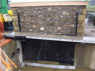
The Screw Trough is now grouted in position and the ties holding
the Screw to the trough have been removed. A Splash Guard has been fixed in position
on the left hand side.
The sides of the Screw Channel are being braced with RSJs.
The Splash Guard can be clearly seen in this picture
Switch Gear is being installed in the Powerhouse.
The Distribution Board on the left will supply the power for the
socket outlets and lighting within the Powerhouse.
The meter that will record the amount of power generated by the scheme
can be seen to the right of the Distribution Board.
Below and to the right of the Meter is the Isolating switch which will isolate the incoming supply.
This picture shows the control panel for the generated electricity.
There will be a cable linking the panel to the generator. The componentry within the unit will
ensure that the generated voltage is of the correct frequency, voltage and power factor.


